Sidebar
Table of Contents
AYLESBURY TOWN
The essential features of the layout are:
• Double track main line
• Main line and branch line platforms including parcels dock
• Double road engine shed.
• Coaling stage
• Goods shed
Track & Baseboard Construction
The layout plan accurately follows the original track plan having been ‘Templot’ designed using Network Rail archive track plans although some artistic licence has been taken given the modelling space available.
The layout baseboards are of a lightweight laminated construction – 3mm ply glued either side of 25mm foam. Joining and accurate alignment of the boards is achieved by the use of alignment dowels and ‘suitcase’ clips.
Whilst this construction proved to be time consuming the result is that boards are easily manageable, quick and easy set up and take down.
For the curved boards a jig was made to enable replication of a consistent angle. These were then edged with 3mm / 9mm / 3mm ply sandwich and a 6mm ply on the outside and inside of the curve respectively.
The baseboards are supported on a combination of trestles and by use of their own storage boxes.
Curved Boards showing laminated construction with ply edgings and suitcase clips
Typical method of support showing use of trestle and baseboard storage boxes.
In July 2016 all the completed baseboards were set up for the first time in the main room of the local Community Centre. The photos give some idea of scale; there are two ten coach trains on the layout and as can be seen these are lost!
Track Construction
The track build uses readily available commercial P4 track components, (rail, chairs, sleepers) with all trackwork on the scenic having been built by club members.
The only exception to this is the trackwork in the fiddle yard which used P4 flexi-track for the straight track and hand built pointwork using copper clad sleepers.
For many club members this provided the opportunity to build trackwork for the first time.
Photo showing the use of Templot design, foam underlay and fettling of hand built trackwork
Lineside
This section describes the principle lineside features and equipment to be found on the layout including background, selection and modelling techniques used:
• Signals
• Water Crane
• Grounded Coach
Signals
At the time of the model, Aylesbury was signalled with BR semaphore signals – mainly ex MR but with a few ex LNER types too – including a large number of ground signals.
The signals are being constructed from brass etches (ladders, arms, balance weights etc.), 3D prints (signal lamps and pivots) and various diameter brass tube, wire and lace pins.
Construction is based on the methods developed by Steve Hewitt (Liverpool Lime Street):-
The method can be seen in the construction of this two doll bracket signal with elevated shunt signal which was sited at the south end of the station.
The left hand photo shows the signal freshly painted; the right hand one weathered
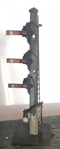
Also at the south end of the station was this interesting concrete post, 3 arm shunt signal.
The model utilises a white metal post and a full description of its construction can be found here:
https://www.youtube.com/watch?v=1-Zvwpe-wlo
Water Crane
The model uses the Mike's Models water crane as a basis with suitable adaptation to match the example at Aylesbury.
Under development - Narrative Required
Grounded Coach
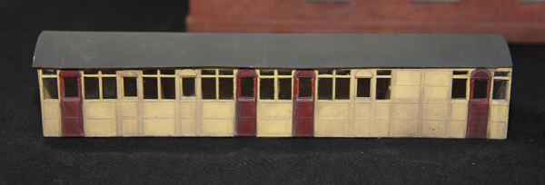
The grounded coach body, thought to have arrived in the 1920’s, was one Metropolitan coach 212. Despite various alterations it remained in situ until broken up in 1967.
The coach body is laser cut from several layers of paper or thin card to build up the various panels and beading before sealing with shellac prior to painting and dry weathering was applied.
Buildings
This section describes the principal buildings to be found on the layout including background, selection and modelling techniques used:
• Main station building
• Lineside Footbridge
• Engine Shed
• South Signal Box
• Up and Down Platform Waiting Rooms
• Water Tower
Main Station Building
Under development - Narrative Required
Lineside Footbridge
The model represents the footbridge at the north end of Aylesbury station as it stood in the 1950’s.
The model has been made using the original drawings albeit the actual bridge span is some 10ft longer than the drawing depicted!
Fortunately, the piers remained relatively true to form.
Various materials were used in the build including brass plate and angles, plasticard and ‘wet and dry’ paper for the asphalt surface. Rivet detailing was recreated using Archer water-slide transfers which despite the small scale, these proved very effective. However, in future, I will apply the rivets just before the final paint coat, as some of the detail was lost.
The brick piers are made of individual components cut on the club laser cutter. The resulting quality is truly excellent, right down to the intricate masonry work which had a curve on the east pier; details which would be extremely difficult to recreate in Plasticard.
Engine Shed
Under development - Narrative Required
South Signal Box
Aylesbury South signal box was a Great Central design, 60ft in length, 12ft wide and contained 55 levers. The top half of the box still exists at Swithland Sidings on the Great Central Railway at Loughborough.
Original drawings could not be obtained for the structure and therefore various photographic sources and even a Bachmann model were used for some of the detail dimensions. After drawing were produced, all parts were produced using the Club's laser cutter; even the tiny brackets supporting the exterior walk-boards are accurate and crisp.
The external cladding was recreated by overlapping 10mm strips of printer paper; a method used to recreate the roof tiles also. The name-boards uses 2mm Wills lettering.
The model the interior uses parts from two Ratio kits, suitably detailed and painted however there are only 40 of the 55 levers due to the available length inside the box. The track diagram was also accurately recreated by editing a photograph of the original plan.
The stairs were produced using Ancorton Models kit, suitably modified to replicate the original structure. Roof guttering, drain pipes and the corner supports were represented using various aluminium rod and brass sections. The chimney was modelled from 2mm diameter brass tube, soldered together to form a T-section. GWR finials were modified to more closely resemble those of the Great Central pattern.
Up and Down Platform Waiting Rooms
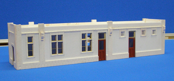
The station platform buildings have been produced by first taking measurements of the actual buildings on site, then recreating them in a CAD package. A ‘kit of parts’ were then laser cut in Rowmark material before assembly.
Under development - Narrative Required
Water Tower
Principle construction uses Alan Gibson etched tank sides on a Plastikard box with a supporting structure from soldered angle brass; ladders by Mike Clarke.
Plastikard pipe and boxes and etched hand wheels from the 51L range.
Painting made use of simple grey enamels and then weathered.
Scenery
Under development - Narrative Required
Rolling Stock
This section describes the background, selection and modelling of the following rolling stock:
• Locomotives
• Coaches
• Wagons
Locomotives
Under development - Narrative Required
Coaches
Under development - Narrative Required
Rolling Stock This section describes the background, selection and modelling of the following rolling stock: • Locomotives • Coaches • Wagons
Locomotives
Under development - Narrative Required
Coaches
Under development - Narrative Required
Rolling Stock This section describes the background, selection and modelling of the following rolling stock: • Locomotives • Coaches • Wagons
Locomotives
Under development - Narrative Required
Coaches
Under development - Narrative Required
Wagons
The freight train movement around Aylesbury tended to be more of a local nature rather than long distance. However, there were a few from and to Marylebone Goods that were more interesting.
Two regular freights over the Princes Risborough branch were hauled by ex GWR 61xx tank loco’s during the night. These were balancing workings for the first and last Paddington Passenger Suburban workings; they went to and from Taplow/Slough. It was also used to exchange loco’s from Slough Shed. There were also trip workings to/from Princes Risborough using a Neasden based loco, sometimes the one used on the Watlington branch freights.
The long distance freights to and from Marylebone Goods, included a night time Marylebone to Mottram (Manchester) and occasionally a Glasgow to Marylebone but this tended to go via High Wycombe; both were V2 hauled.
Quainton Road was the staging post for freights (mainly coal), to and from Harrow/Watford and Neasden with corresponding returns (mainly empty). There was also a Woodford to Harrow/Neasden and return. Again these ran mostly at night or early in the morning with very little in the afternoon or early evening because the Metropolitan (London Transport) didn’t want them to interfere with and slow up their intensive passenger workings. These freight’s were mostly hauled by L3, L1, LMS or BR large tanks plus Ivatt or BR 2-6-0 tender loco’s (and anything else Woodford or Neasden had on hand eg B1’s and W.D’s). These trains amounted to around seven in each direction.
Because the amount of wagons required to run the Aylesbury Project is quite large, it was decided to obtain a number (30) of BR vans, steel, 7 plank and 8 plank mineral wagon kits from Parkside Models. Also obtained were P4 wheelsets, 3 link and Instantler couplings, etched V hangers, door bangers, brake handles and ratchets. Transfers were also obtained. A “minimum” specification for completed wagons was drawn up although any amount of improvements on top of this could be made.
This first batch of kits were then issued to interested club members to complete before consideration is given to extending the exercise to cover all of the wagons needed to represent typical types used during the layouts period.
Operation & Control
Aylesbury Town is a P4 sectional - transportable - layout operated with Digitrax DCC, taking advantage of Digitrax's Loconet to reduce the interboard electrical complexity.
Within each board there is a common electrical layout:
•There are two separate power districts on each board: up-side and down-side, separated along the 6-foot way between the up and down main lines. The Princes Risboro’ branch and locoshed area are all part of the down-side district.
•Any crossovers that connect the up and down sides are double- gapped between the two tracks to preserve the separation of the two power district.
•Nothing else is connected to the track power districts other than track. This is either by direct droppers to the track itself, or connections to components that switch track power polarity such as point frog switches in point motors.
• The track bus wires are each labelled with one “Red” and “Black” rail; all rails on the outside of the layout are connected to the relevant Red bus; all inside rails to the relevant Black bus.
• A third “Accessory” bus, centrally mounted on the boards, carries AC power, nominally at 15v. All other electrical/electronic equipment is connected to this bus and is capable of handling AC power at up to 15v and up to 8Khz.
Bus Connections between boards:
• The three bus pairs are connected between the boards with Anderson Power Pole 15Amp connectors in a 2×3 block, with the outer pairs carrying the two track buses and the middle pair the accessory bus; the PowerPole connectors are coloured to suit.
• One loconet connection is made between each board.
• No other connections are allowed; this then enables each board to be operated, if required, in a stand-alone mode for testing and maintenance work by connecting appropriate power supplies to the PowerPole connectors and Loconet at one end of the board.
DCC components on each board:
• These vary from board to board; each board has all three power buses and Loconet available.
• Accessories are powered from the accessory bus, noting that this bus is nominally 15vAC; appropriate current and voltage control is be provided to suit.
Turnout control:
• Points are operated using DCC Concepts Cobalt Analog switch motors; these are mounted below the relevant turnout with power supplied from a Digitrax DS64 Accessory decoder. • The DS64s are powered from the accessory bus • The DS64 is connected to Loconet and as described by Digitrax: “this is where it gets the turnout command signals from”.
Signal Control:
This is expected to be by servo accessory decoders connected to the relevant bus wires using servo decoders that accept commands from Loconet and that don't require DCC track power to operate.


